 English
 русский
Industry News
Valve Manual Mechanism Turbine Head
2026-06-26
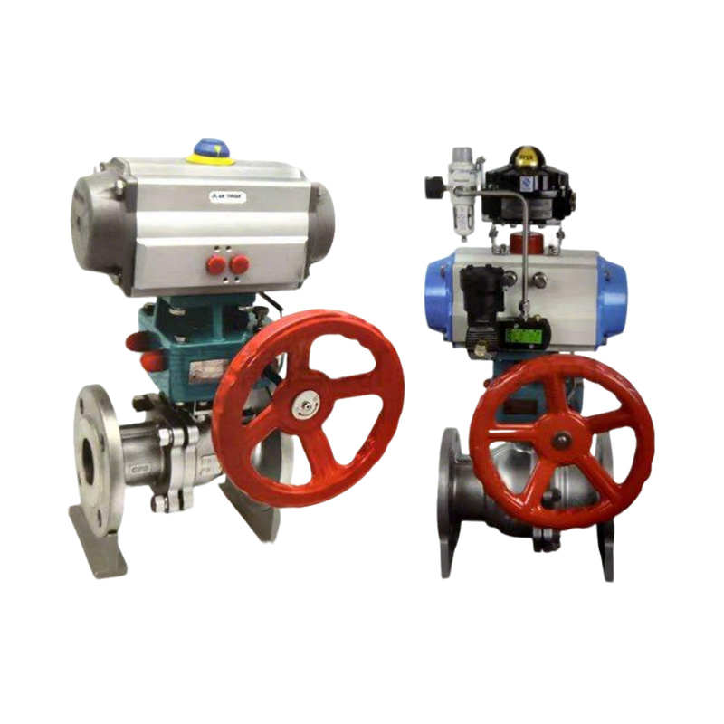
Turning a large valve by hand is not always easy. As valve size goes up, the force needed to open or close it goes up too. A valve manual mechanism turbine head solves this problem. It uses a worm gear and wheel to multiply the force from the handwheel. The operator turns the handwheel. The turbine head transfers that motion to the valve stem. The valve moves. But the effort required is much lower than turning the stem directly.
A valve manual mechanism turbine head is standard equipment on many industrial valves. Gate valves, globe valves, and butterfly valves in sizes above a certain point usually come with one. Without it, operators would need a long wrench or a gearbox to move the valve. With it, one person can operate a large valve with reasonable effort.
How the Mechanism Works
Inside a valve manual mechanism turbine head, there is a worm and a wheel. The worm is a threaded cylinder that looks like a screw. The wheel has teeth that mesh with the worm threads. The handwheel connects to the worm. The valve stem connects to the wheel.
When the operator turns the handwheel, the worm spins. The worm turns the wheel. The wheel turns the valve stem. Because of the angle between the worm and wheel, the mechanism locks automatically. The valve cannot back-drive. Even with pressure pushing against the valve disc, the stem will not turn on its own. This self-locking feature is important for safety.
Key components of a valve manual mechanism turbine head include:
- Worm shaft with bearings at both ends for smooth rotation
- Worm wheel cut from bronze or cast iron
- Housing that seals the gear set from dirt and moisture
- Handwheel mount and stem connection flange
- Position indicator showing whether the valve is open or closed
Gear Ratios and Torque Output
Different valve manual mechanism turbine head models offer different gear ratios. A low ratio like 10:1 means ten turns of the handwheel produce one turn of the valve stem. The operator gets a ten times force multiplication but makes ten times as many turns.
A higher ratio like 30:1 gives more force multiplication. The operator turns the handwheel more times but applies less effort each turn. The right ratio depends on the valve size and the pressure against the valve disc. A large high-pressure valve needs a higher ratio than a small low-pressure valve.
Manyvalve manual mechanism turbine head units have ratios between 10:1 and 60:1. The manufacturer selects the ratio based on the valve torque requirements. Too low a ratio and the operator struggles to turn the handwheel. Too high a ratio and the valve takes too long to open.
Materials and Environmental Protection
A valve manual mechanism turbine head lives outdoors in many installations. Water treatment plants, chemical facilities, power stations, and oil refineries all use these devices. The housing must protect the gear set from rain, dust, and corrosive atmospheres.
Cast iron is common for general-duty valve manual mechanism turbine head housings. It machines well and provides good strength. Ductile iron offers higher impact resistance. Stainless steel housings are used for corrosive environments or where the valve must meet sanitary standards.
The worm wheel is usually bronze. Bronze has low friction against steel, which helps efficiency. It also resists wear better than other materials. Some valve manual mechanism turbine head units use cast iron wheels for lower-cost applications, but bronze is preferred for reliability.
Sealing is critical. A valve manual mechanism turbine head that leaks allows moisture inside. Moisture causes rust and oil breakdown. units use O-rings or lip seals on the input and output shafts. The housing gasket must stay flexible over years of temperature changes.
Common operational considerations:
- Always turn the handwheel smoothly without jerking
- Do not use a wrench or cheater bar on the handwheel
- Stop turning when the mechanical stop is reached
- Lubricate according to the manufacturer's schedule
Maintenance and Service Life
A valve manual mechanism turbine head needs periodic maintenance. The gear oil or grease eventually breaks down. manufacturers recommend lubricant changes every one to two years, depending on operating conditions.
Seals wear out over time. A leaking valve manual mechanism turbine head will eventually lose lubricant and fail. Operators should check for oil leaks around the shafts and housing joint. Early replacement of worn seals prevents gear damage.
If the valve manual mechanism turbine head becomes hard to turn, something is wrong. The gear set may have worn. Bearings may have failed. The lubricant may have dried out. Continuing to force the handwheel will damage the valve stem or the turbine head.
An Essential Valve Component
For valves beyond a certain size, a valve manual mechanism turbine head is not optional. It is the difference between a valve that one person can operate and a valve that requires a team or a power tool. The simple worm gear design has been working for decades because it is reliable, self-locking, and effective.
CATEGORY
Recent Posts
-
2026-06-26
Message Feedback
Copyright © Zhejiang Xiafeng Precision Die Casting Co., Ltd.
China Air Operated Double Diaphragm Pump
